Precise Decade Frequency Generator

Here is a circuit to generate accurate frequencies of 1 Hz,
10 Hz.,
100 Hz, 1 kHz and 10 kHz based on a crystal oscillator and a PIC
programmed as a decade frequency divider. A stable frequency reference
has many uses around the lab, and relatively low power consumption
makes battery power an option. Since it uses an ovenized reference
(OCXO) it is more stable than a simple crystal oscillator. My samples show a drift rate of about 1E-9 (1 ppb) per hour.
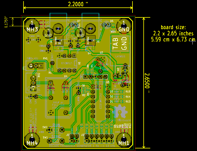
I
laid out the PCB with dual 7-15 V power inputs to facilitate moving
the timebase from one place to another, switching from wall
power
to a battery power pack without powering down the oscillator and
loosing synchronization. The small ovenized oscillator I used
(Pletronics OHM40480526) draws 70 mA when running, and 6xAA batteries
could run the circuit for about 24
hours. The frequency is set by comparing the 1PPS output to a GPS
reciever 1PPS, and adjusting the coarse and fine trim controls until
the relative drift is zero. Initial tests suggest
this part can reach short-term frequency stabilities of 1 ppb (1E-9)
over one hour, although the PLE OCXO spec is 100 ppb per 24 hours.
Drift is generally better after the oscillator has been powered up for
some time (several days). At the
time I
designed this circuit, this OCXO was available inexpensively from
ebay seller petlor.
If you need better accuracy you can use for example a
"Thunderbolt" GPS-disciplined oscillator (used devices online start
around $100), but it is larger, requires
GPS reception for long-term stability, and draws 10 watts.
The
board will accept any full- or half-can DIP oscillator, although some
modification may be needed depending on the particular part. The source
code can be compiled for 10 MHz as well as 26 MHz clocks, and other
frequencies could be accomodated by tweeking the code. The PCB provides
two footprints at right angles for the 7805 regulator, to allow for
laying flat and heatsinking to the PCB, or standing up and connecting
an external heatsink.
The circuit uses a PIC programmed as the decade divider. The original
code and basic
PIC connections are from Tom Van Baak at leapsecond.org,
as modified by Richard
McCorkle
and myself. If
you care about edge risetimes: this PIC does about tr = 17 ns. In
comparison, the ATmega328P (of Arduino fame) has about 5 ns risetimes,
and a CPLD output may do 1 ns or better. I provided the
option to
run the PIC at 3.3V or 5V to allow selection of the output voltage
level. A possibly better way would be to run at 5V and use a buffer
chip, like a 74LCX125
or 74LCX14
to provide 3.3V outputs, which would also have
faster risetimes.
As
of November 2011, total BOM parts cost is about $25 per board, if you
build 10 units at a time, excluding assembly costs. Less if
you
have the many common components in stock and purchased in larger
quantites. Note a few parts (marked "0" qty.) are on the
schematic, but not used. Also, if you run the PIC at 5V instead of
3.3V, you can eliminate the 3.3V regulator, and remove R3, C8 and
substitute a 0-ohm for R2. You stuff either R4 or R6 (of
course
not both) to select the PIC operating voltage.
You
could also use the LM7805 +5V power rail instead of the LT1021 +5V
reference, at a cost in stability of course. One sample of
the
PLE 26 MHz oscillator I measured has a sensitivity of about 3 ppm /
volt on Vtune (U4 pin 1), although it varies over the control range
(for more details see 26MHz-OCXO-tuning.xls).
So a 1 mV variation on Vtune will cause a frequency shift of 3 ppb.
")
 (Click on a plot for a larger image)
Drift
comparison: the plot at left shows the frequency offset between two
PLE 26 MHz OCXO oscillators, using two prototype versions of this
circuit.
One of the prototypes did not have the +5V reference for the control
voltage, using instead the +5V power rail supplying the oscillator
power and the internal heater. The two
oscillators change frequency relative to each other by about 3 ppb
(parts per billion, 1E-9) over the course of 32 hours. At least part of
this drift is due to ambient temperature change since varying current
drawn
by oven changes the +5V rail. The plot at right shows the
same
two oscillators, but now both using a LT1021 +5V reference to establish
their control voltage. This improves the relative drift, with the plot
showing a 1.5 ppb change in frequency over 72 hours. The
(indoor)
ambient temperature ranged between 19.6 C and 21.8 C during the second
plot period (Nov. 12-15). I believe the temperature change was similar
for the first plot, but did not record it.
Note if
you adjust two of these circuits to within a few ppb of each other,
with outputs connected to a third instrument (sharing a common ground)
stray coupling may cause the two OCXOs to phase-lock and you will read
near-zero relative drift. Of course that is not a true measure of their
independent stability.
UPDATE Nov. 25 2011 26MHz 1PPS generator PCB "dd1 v.1" (OCT.30 2011)
Circuit works, after this rework:
1) J1,J5: pins 2,3 reversed. FIX: remove unused side pin on jack, and short pins 2+3 on PCB
2) RV2: footprint pins straight, should be staggered. FIX: bend pin 2 on pot to fit footprint
3) U5 pin 3 missing pullup. FIX: add 10k between U5.3 and U5.1
John Beale
last updated:
Oct. 31 2011


")
